Project Overview
The device was functioning before an attempted upgrade from an older release (recalled as approximately 1.8.6) to 1.9.1. Its browser-based updater remained on an updating screen for approximately twenty minutes. A manual reset left the LCD illuminated but blank.
The goal was not to replace the device or rewrite its firmware. It was to preserve the failed chip image, compare it with the original update package, then restore a bootable image using an external programmer.
Recovered Hardware
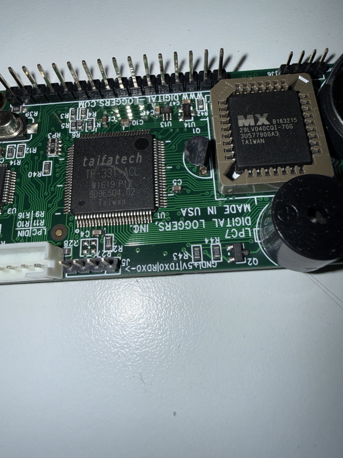
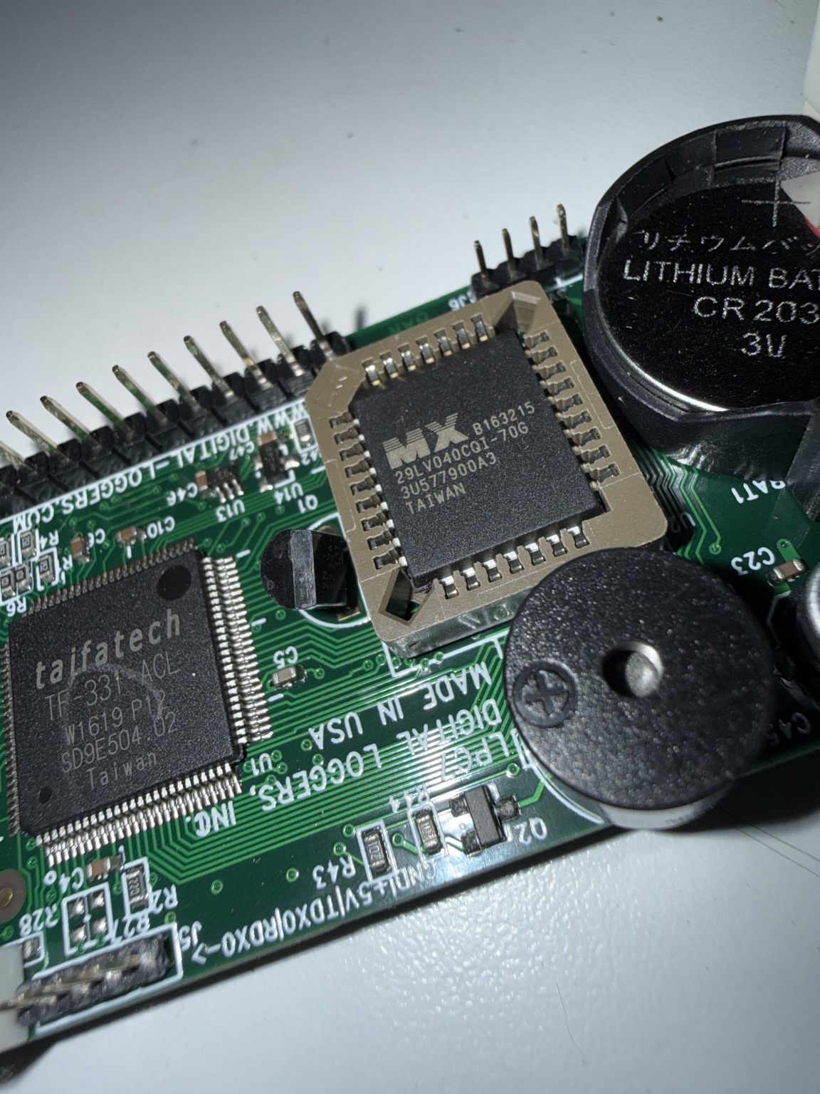
Removing the LPC controller board exposed a socketed Macronix NOR flash next to the Taifatech TF-331-ACL device, a CR2032 battery and the display-control circuitry. A PLCC32 socket made a non-soldering recovery possible.
| Component / interface | Identification | Significance |
|---|---|---|
| Parallel NOR flash | MX29LV040CQI-70G | 4 Mbit / 524,288 bytes; removable PLCC32 |
| Controller-related IC | Taifatech TF-331-ACL | Visible on the board; exact functional role not established from photos |
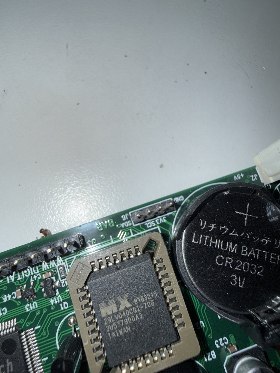
| J6 | SDA / 3V3 / SCL markings | Likely I²C header; complete pinout unverified |
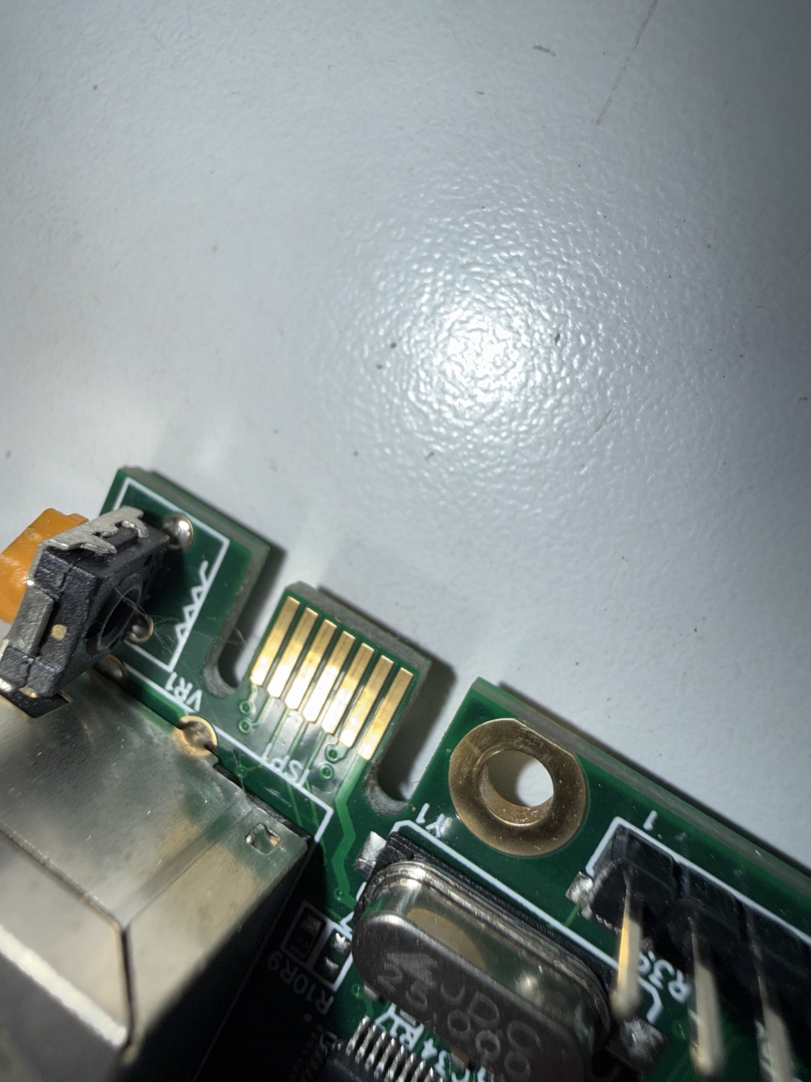
| ISP edge pads | ISP silkscreen | Potential in-system programming route; protocol unverified |
| Backup power | CR2032 | Likely RTC / backup use, exact configuration storage not proven |
First Rule: Preserve the Failed Image
The chip was read three separate times with the T48, and each resulting file contained exactly 524,288 bytes. All three hashes matched. This made the failed contents a reproducible forensic artifact rather than a one-off read.
| File | Size | SHA-256 |
|---|---|---|
MX29LV040@PLCC32.BIN | 524,288 | 84fc5b3ce8b92ccd1c1cf517d8472174846235f1313e7dd661e2ccc1f9e136a1 |
MX29LV040@PLCC32_bak.BIN | 524,288 | 84fc5b3ce8b92ccd1c1cf517d8472174846235f1313e7dd661e2ccc1f9e136a1 |
MX29LV040@PLCC32(1).BIN | 524,288 | 84fc5b3ce8b92ccd1c1cf517d8472174846235f1313e7dd661e2ccc1f9e136a1 |
The update source file was also 512 KiB:
LPC-1.9.1.BIN — 524,288 bytes
SHA-256: a434e702a466a02206ddb7196df72ade1ec9edcd15306b2d2eae7eb5c11f6e5e
Keep the old dump as an archival master. A firmware update file and a raw physical flash dump may look similar but are not necessarily interchangeable on every appliance.
Binary Forensics: The 538-Byte Displacement
Comparing the failed chip and the 1.9.1 update package produced an unexpectedly structured result. The first 65,536 bytes (0x00000–0x0FFFF) match exactly. Their first difference occurs at offset 0x10000.
At that boundary, the failed dump starts with bytes that appear at 0x1021A in the update file: a displacement of 538 decimal / 0x21A bytes.
Exhibit A — identical firmware header
Both files start with the following actual bytes. ASCII embedded in the dump includes DIGITAL LOGGERS.
000020  FF FF FF 02 01 60 24 44 49 47 49 54 41 4C 20 4C  |.....`$DIGITAL L|
000030  4F 47 47 45 52 53 20 4C 50 43 30 58 75 9D 02 75  |OGGERS LPC0Xu..u|
000040  D0 00 90 00 FF F0 74 00 93 F8 74 01 93 52 00 74  |......t...t..R.t|
000050  02 93 52 00 74 03 93 58 B4 FF 06 D2 11 02 01 00  |..R.t..X........|
Exhibit B — what is at offset 0x10000?
The original update file contains the following 64 bytes:
010000  D2 11 90 00 70 6D 74 6A F0 90 00 70 6F 74 60 F0  |....pmtj...pot`.|
010010  90 00 70 70 74 0F F0 D2 99 75 81 49 02 01 54 17  |..ppt....u.I..T.|
010020  02 01 03 ED E8 64 80 F8 E9 33 E8 33 60 11 04 60  |.....d...3.3`..`|
010030  EF ED 33 EC 33 70 09 E8 FC E9 FD EA FE EB FF 22  |..3.3p........."|
The failed chip instead contains these 64 bytes at the same address:
010000  02 01 03 F7 EC 2C FC EF 33 FF EE 33 FE ED 33 FD  |.....,..3..3..3.|
010010  02 01 03 CF 02 01 03 F7 EC 5D 04 60 05 E8 59 04  |.........].`..Y.|
010020  70 04 02 01 03 ED 12 01 03 B8 58 04 60 F4 EC 48  |p.........X.`..H|
010030  60 F0 EC 70 04 FD FE FF 22 C8 60 D8 24 81 C8 50  |`..p....".`.$..P|
Exhibit C — matching bytes after shifting by 0x21A
Move the update-file view forward 538 bytes and its bytes line up with the failed chip, byte-for-byte:
010000  02 01 03 F7 EC 2C FC EF 33 FF EE 33 FE ED 33 FD  |.....,..3..3..3.|
010010  02 01 03 CF 02 01 03 F7 EC 5D 04 60 05 E8 59 04  |.........].`..Y.|
010020 70 04 02 01 03 ED 12 01 03 B8 58 04 60 F4 EC 48 |p.........X.`..H|01021A 02 01 03 F7 EC 2C FC EF 33 FF EE 33 FE ED 33 FD |.....,..3..3..3.|
01022A 02 01 03 CF 02 01 03 F7 EC 5D 04 60 05 E8 59 04 |.........].`..Y.|
01023A 70 04 02 01 03 ED 12 01 03 B8 58 04 60 F4 EC 48 |p.........X.`..H|Machine-verified alignment
failed[0x00000:0x10000]
  == update[0x00000:0x10000]       TRUE

failed[0x10000:0x7FDE6]
  == update[0x1021A:0x80000]       TRUE

Alignment shift: 0x21A = 538 bytes
Second matching span: 458,214 bytes
The second comparison reaches the end of the update file. These are measured byte relationships, not assumptions about how the updater operates.
Duplicated code at the end of flash
There is another notable property: the failed dump contains an exact repeat of its first 65,528 bytes, beginning at 0x6FDE6. The supplied update file also contains an end-region copy, but aligned differently. This suggests some kind of duplicated firmware region; it does not establish its intended bootloader or recovery function.
Exhibit D — duplicate-region boundary
06FDE6  02 00 3C 02 01 60 04 FF 00 22 FF 01 00 92 74 67  |..<..`..."....tg|
06FDF6  69 2F 00 02 01 60 14 FF FF FF FF 02 01 60 1C FF  |i/...`.......`..|
06FE06 FF FF FF 02 01 60 24 44 49 47 49 54 41 4C 20 4C |.....`$DIGITAL L|070000 02 00 3C 02 01 60 04 FF 00 22 FF 01 00 92 74 67 |..<..`..."....tg|
070010 69 2F 00 02 01 60 14 FF FF FF FF 02 01 60 1C FF |i/...`.......`..|
070020 FF FF FF 02 01 60 24 44 49 47 49 54 41 4C 20 4C |.....`$DIGITAL L|Repeat the analysis
With both files present, the following Python script reproduces the two strongest findings and protects against misinterpreting a hex editor screenshot.
from pathlib import Path
import hashlib
failed = Path("MX29LV040@PLCC32.BIN").read_bytes()
update = Path("LPC-1.9.1.BIN").read_bytes()
assert len(failed) == len(update) == 0x80000
assert failed[:0x10000] == update[:0x10000]
assert failed[0x10000:0x7FDE6] == update[0x1021A:0x80000]
assert failed[0:65528] == failed[0x6FDE6:0x6FDE6+65528]
for title, payload in (("failed", failed), ("update", update)):
    print(title, hashlib.sha256(payload).hexdigest())
print("Verified: 64 KiB common prefix; 0x21A shifted alignment")Field Notes: External Flash Recovery
Because the chip was socketed and the full-length firmware binary was available, the repair could proceed without a working serial console, Ethernet interface or bootloader.
Disconnect AC, note the chip's pin-1 orientation, and extract the PLCC32 from its socket with the proper tool.
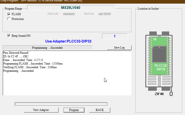
Use MX29LV040 in XGpro with the PLCC32-DIP32 adapter and verify the device ID. The captured log reported 0xC2 0x4F — OK.
Make repeated reads before erasing anything. All three archived reads matched.
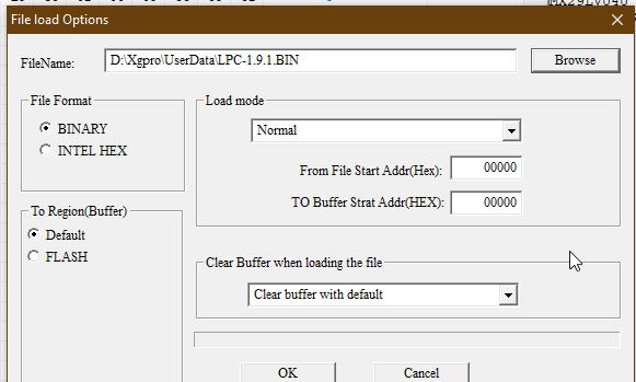
Select Binary / Normal; file offset 00000; buffer offset 00000; clear buffer before loading.
Erase the flash, program addresses 0x00000–0x7FFFF, and verify the complete buffer. XGpro reported success at every stage.
With power disconnected, reinstall the chip in the original orientation, safely reassemble and start the controller. Confirm both firmware and saved settings.
Programmer evidence
Pins Detected Passed!
ID: 0x C2 4F ......OK!
Erase ...Succeeded. Time : 4.171 S
Programming FLASH ...Succeeded. Time : 15500ms
Verifying FLASH ...Succeeded. Time : 2188ms
Programming ...Succeeded| Recorded operation | Result |
|---|---|
| Chip identity | MX29LV040, manufacturer/device ID accepted |
| Adapter | PLCC32-DIP32 |
| Flash range | 0000000–0007FFFF |
| Erase | 4.171 seconds, succeeded |
| Programming | 15.500 seconds, succeeded |
| Verification | 2.188 seconds, succeeded |
First Boot: Blank, Then Alive
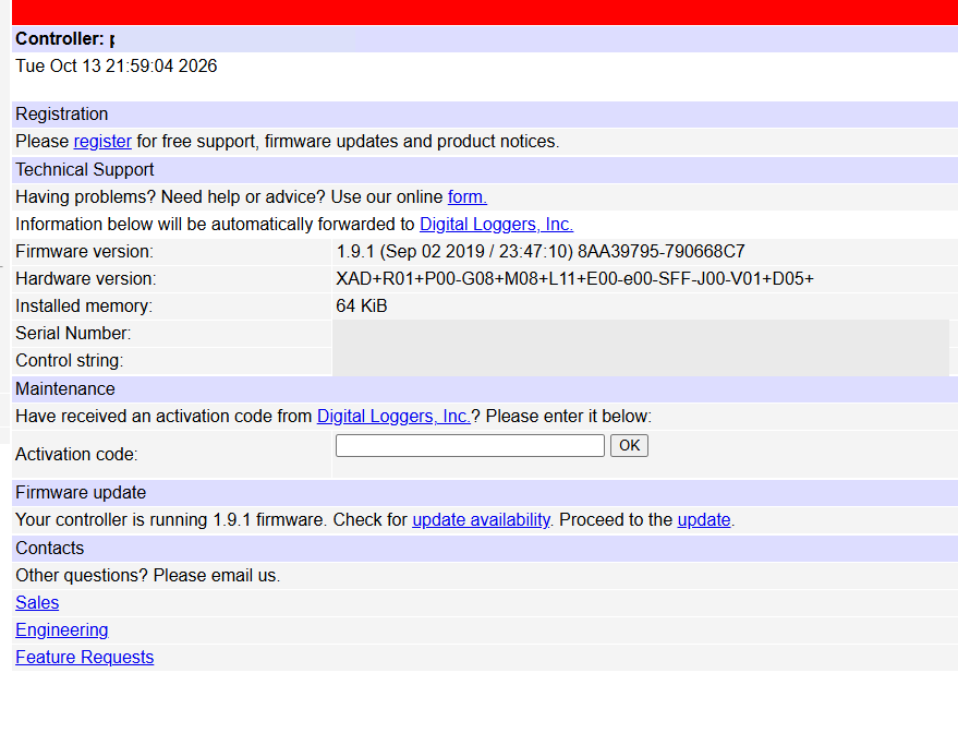
The first power-on after programming initially looked unsuccessful: the LCD backlight was on but there was no text. After roughly thirty seconds it displayed “Booting 1.9.1”, and the controller became usable again.
Subsequent starts were immediate. The one-time delay is consistent with initialization after reflashing, but its internal cause was not traced.
Confirmed versus inferred
| Observation | Status |
|---|---|
| Flash image reprogrammed and verified successfully | Confirmed by T48 log |
| Device boots 1.9.1 and settings remain | Confirmed by owner and interface |
| 538-byte offset relationship in failed dump | Confirmed by byte comparison |
| Failure caused specifically by missing 538 bytes | Unproven |
| Configuration lives in a separate EEPROM | Plausible, unproven |
| First 30-second delay reflects a migration | Plausible, unproven |
Preservation Package and Reproducibility
For public distribution, this page embeds photographs and byte excerpts and includes an executable analysis recipe. The companion recovery archive contains the original full-length chip dump and firmware update file for private archival use. Check distribution rights before publishing vendor firmware binaries publicly.
Archived evidence
MX29LV040@PLCC32.BIN — original failed read
MX29LV040@PLCC32_bak.BIN — repeat read
MX29LV040@PLCC32(1).BIN — additional repeat read
LPC-1.9.1.BIN — source update image
sha256-manifest.txt — cryptographic checksums
compare_lpc.py — byte-level verifier
The original chip dump should never be replaced with an edited or “fixed” copy; preserve it as evidence of the failed state.
Conclusion
The failed LPC was not repaired by guessing at a network recovery protocol. It was repaired by identifying its socketed flash, preserving its contents, measuring the layout difference against the original update package, and programming the complete image externally.
The most useful moment came after a discouraging first thirty seconds of blank LCD: Booting 1.9.1. The original configuration survived, and the appliance returned to normal startup behavior. On this board, external NOR flashing provided a practical recovery path when the internal updater could not.